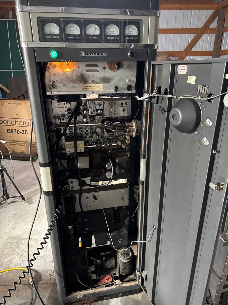
Every so often, while doom scrolling through Facebook Marketplace (as one does), you stumble across something that stops you dead in your tracks. For me, it was this massive 1950s Motorola VHF base station weighing in over 300 pounds of old school vacuum tube radio engineering, still standing tall and looking surprisingly complete for its age.
The seller was asking next to nothing for it, which made it even more unbelievable. The only catch? It was in Tomahawk, Wisconsin a long haul from where I live. I happened to be eating dinner with a friend at the time and mentioned it to him. Without missing a beat he said, “Well, let’s go right now!”
I laughed at first, assuming he was joking. But for a moment I really sat there thinking, what if we actually did it? A spontaneous road trip for a 300-pound antique transmitter… equal parts amazing and completely impractical. In the end, we didn’t make that impulsive midnight run.
A day later, the seller messaged me to say it had been sold. I wasn’t surprised just disappointed. I sighed and resigned myself to the idea that this giant piece of radio history had slipped away.
Then she offered to pass my contact information to the buyer.
The next day, I got a message. The new owner told me he had intended to part it out, and I made my pitch: I’d take the whole thing, as-is, and even triple what he’d paid still under $200. He agreed, but there was one complication: he was scheduled for double knee replacement surgery that week. We agreed to reconnect in mid-to-late November 2025.
When November came around, I reached back out. We picked a date, loaded up for a 1,200-mile round trip, and hit the road. Now this big old Motorola beast is sitting in my garage.
To my surprise and excitement, it came with the original manuals and schematics, the kind of documentation you almost never find with equipment this old. I’ve searched for information on these units before and found very little just a handful of Reddit and Facebook posts. Now I have the real thing and the paperwork.
The plan?
A complete restoration and if all goes well putting this 1950s transmitter back on the air, making RF once again. I plan to convert it into a VHF repeater.
I couldn’t be more excited!


I had the manual scanned! Here is a digital copy for anyone who may like or need it.
Update – It works! November 1st 2026
Quite a bit has happened in the almost year that has passed since acquiring this big ol beauty! Including a big move to rural Nebraska, where I now have a shop building to work on things such as this.
For anyone just finding this, it’s a 1958 Motorola B93AKB base station. 250 watts on VHF, all tubes, in a cabinet that stands almost 6 feet tall and weighs over 300 pounds. When I started on it this time, the receiver worked great. I could hear my handheld through the front speaker no problem. Transmit was another story. Key it up and the blowers kicked on, the relays clunked, the high voltage contactor pulled in… and zero RF. Nothing.
Here’s how it went from that to on the air.
First things first: new caps and some cleanup
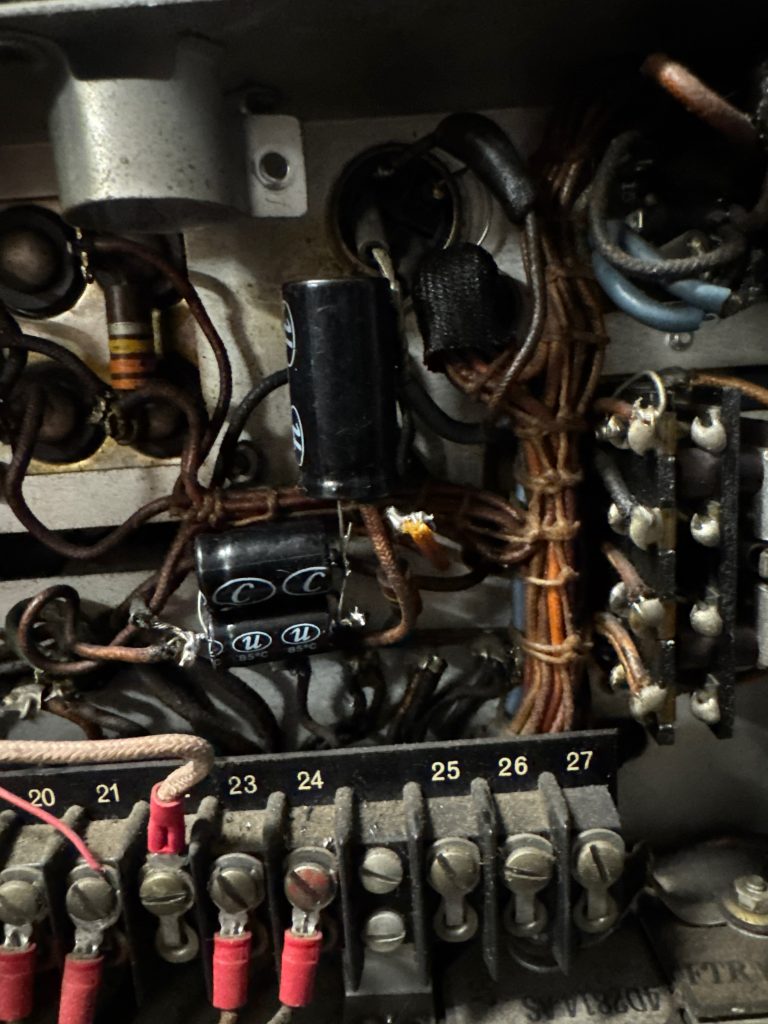
Before any of this, back before the move, the very first thing I did was replace the filter capacitors on the receiver and exciter power supply chassis. The originals were bad from age, which is pretty much a given on anything from 1950’s. Old electrolytics dry out and leak, and firing up a tube radio on bad caps is a good way to cook a transformer or a rectifier.
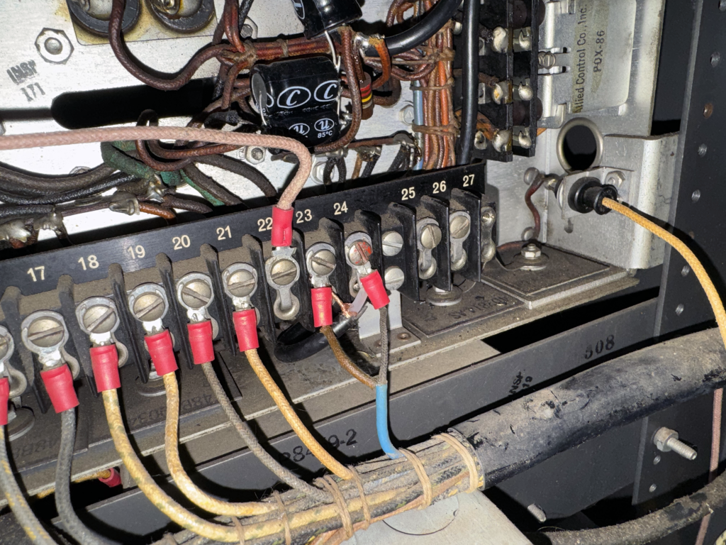
Around the same time, I pulled out a bunch of random switches and extra wiring that someone had added on over the years, so the connections on TB3 (the main terminal board on the exciter power supply) actually matched what the manual shows. With new caps in and the wiring back to stock, it was safe to power up and start troubleshooting.
The manual didn’t quite match
I already had paper manuals for this station, which I had professionally scanned (it’s linked earlier in this post). It was a huge help, but two of the big chassis in my unit aren’t the ones in the book. My exciter is a TTD6080AA, not the TTD1340AA the manual covers, and my high voltage supply is a P-8313-C instead of a P-8238-C. Close enough to work from, different enough to keep me guessing. My HV supply even has an extra terminal strip the manual doesn’t show, and I spent way too long chasing a “mystery” wire on it that turned out to be nothing. A floating wire next to AC lines will happily show you voltages that aren’t really there.
Following the meters
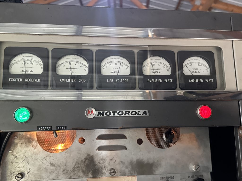
This station has a built-in meter panel with a selector switch that lets you check every stage of the transmitter. That ended up being the key to the whole thing.
The plate voltage meter showed about 2500 volts when keyed, so the high voltage supply was fine. The problem was further back. The exciter, the low power chain that builds up the signal and drives the big amplifier, was barely making anything. Going stage by stage on the meter, the signal was weak at the first multiplier and completely gone by the next one. No drive to the final means no RF out.
I’ll admit I lost a whole evening of measurements because I had my probes in the wrong tube socket. A new day and a fresh meter battery helped a lot.
The mic wouldn’t key it
Another early head scratcher, I could key the transmitter with the spring loaded switch on the meter control panel, but pressing the button on the mic did nothing. Same transmitter, two different ways to key it, and only one worked. Tracing it back, some wires were missing on TB3, the main terminal board on the exciter power supply, going to the door interlock switch. The cabinet has interlocks on the doors so you can’t key it up while someone’s working inside, and with those wires gone the mic’s keying circuit never got completed. I re-patched the missing connections and the mic keyed it right up.
The real problem: the crystal
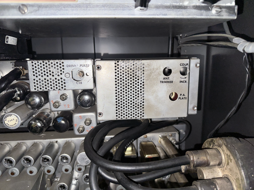
The transmit crystal was marked 145.770, which is in the 2 meter ham band. At some point someone put a ham crystal in this thing, but the exciter coils were never retuned for it. They were still sitting wherever they were in this stations past life. Each multiplier stage just lost a little more until there was nothing left.
All the tubes tested good on my tube tester, so once I had proper plastic alignment tools, I started peaking coils. The first one went from barely moving the needle to way past where it needed to be. The stage that had been reading a flat zero came right up. Then it made RF for the first time!
I swapped in a 146.520 crystal I had and aligned the whole exciter for that.
No audio
Now it keyed and made RF, but talking into the mic did nothing. I traced the mic wiring and found the shielded cables going to the transmitter connector were borked. The insulation between the center wire and the shield had degraded and broken down shorting the audio straight to ground. There was also a mess of old twisted splices and gooey tape at the connector. I pulled all of it and ran new shielded cable and audio came right back.
The final amplifier
The big amplifier uses a pair of 4-125A tubes running around 2000 volts on the plates. That’ll get your attention!
While tuning it up, the grid meter kept pinning off scale, even with the exciter disconnected. Turns out there’s a little SCREEN / GRID switch on that meter I had never noticed and it was set to SCREEN flipping it to GRID, the reading made sense. Next was checking the neutralization. In a tube amp a little of the output sneaks back to the input through the tube itself, and at VHF that can make the amp unstable or even turn it into its own oscillator. The fix is a small adjustable capacitor (C4 on this amp) that feeds back an equal and opposite bit of signal to cancel it out. To check it, you leave the high voltage off, drive the amp with the exciter, and swing the plate tuning back and forth while watching the grid meter. If the needle dips, it needs adjusting. Mine barely moved, so it was already neutralized and I left it alone.
My first test load was a 200 watt light bulb. It lit up on the low setting at about 50 watts, and on high at 200 to 250 watts it definitely lit up. The wattmeter showed a fair amount coming back, though, since a light bulb isn’t a great match at 2 meters, so it was only good for a quick test.
The T/R switch
At some point someone added a B&W Model 377 coax relay to swap the antenna between transmit and receive. It may very well have been wired up right before, but I disconnected it way back while fixing other things, and when I hooked it back up it never switched correctly. The station switches the neutral side of the 117 volt line on transmit, not the hot side, and I had the relay wired between that line and ground, so it never saw voltage. I moved one wire to the hot side and now it clicks over every time I key.
The scare
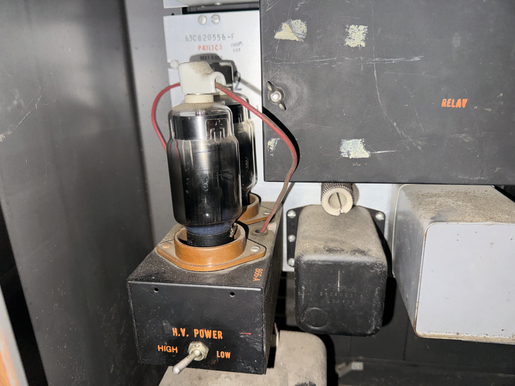
After working on the bottom blower, I powered it back up and the 3B28 rectifier tubes started arcing inside, with the meters jumping all over. I shut it down fast. Filament voltage checked out fine. I pulled the tubes, checked them, reseated them, and it’s been perfect since. Most likely a bad connection at a socket that got disturbed while I was moving wires around down there.
Receiver touch-up
The receiver worked from day one, but since I changed frequency I went through it anyway: peaked the oscillator, the five RF tuning pipes, and centered it on frequency with the discriminator meter. It was already close, so not much changed. Good sign for something this old.
Fun numbers
It pulls a little more than 200 watts from the wall just sitting there idle and about 1350 watts (around 11 amps) while transmitting. Only about 250 of that leaves as RF. The rest is heat, so in the winter it’s basically a space heater that talks.
What’s next
I have decided (for now anyway) to not convert this station into a repeater, I will be using it on the 2 meter calling frequency, next items to address.
- A proper antenna!
- Final tune-up on high power into a real 50 ohm load.
- Setting exact frequency and deviation with an SDR.
- Cabinet cleanup, the bottom of the unit is a little rusty from sitting on cement for so long.
- Maybe recording receive audio onto a reel-to-reel through the remote line input, just because I can.
It’s been a long road, but this 68 year old radio is back on the air. More soon.
73, K9FAX
Update 2 – it was half deaf! November 2nd 2026
While I wait on antenna parts, I got my Comet SBB-5 mounted on the metal roof of the shop. That antenna is only rated for 120 watts, so I turned the station down by putting the exciter on its LO setting and retuning the final, which brought it right into range.
The bigger problem was receive. A little handheld with a stubby antenna standing on a 6 foot platform could hear stations this thing couldn’t hear at all, all on 146.520. Someone had added a V.J. Products 2 meter preamp in front of the receiver at some point, but pulling it out made no difference either way.
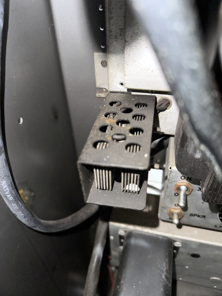
The receiver’s own meter readings were low across the board, so I measured its B+ supply. It’s supposed to be about 180 volts, and it was sitting at 102. With the receiver unplugged it jumped to 197, so the supply couldn’t hold up under any load. The culprit was an old selenium rectifier stack mounted on the front of the power supply chassis. Selenium rectifiers wear out with age, and these ones were done. I wired in a modern 800 volt silicon bridge rectifier in its place, using the same four leads, and B+ came right up to 174 volts.
That helped a lot, but the RF tuning pipes still didn’t seem to do anything when I adjusted them. Turns out my handheld was so close it was leaking straight into the chassis and swamping the meter, so I wasn’t really tuning anything. I borrowed my buddies Rigol DSA815 spectrum analyzer and used its tracking generator as a clean, low level signal source right into the receiver input. With a proper test signal, the front end tuning came way up and the receiver gained a LOT of signal. Years of running on low voltage and a front end that was way out of tune had it basically half deaf this whole time!